200 Transistor Circuits Circuit Diagram
200 Transistor Circuits Circuit Diagram Figure 1 shows an easy way to drive a transformer without having to use a coupling capacitor. When the drive signal goes high, the small-signal FET, Q2, turns on, and the drive voltage is applied across the winding of the transformer. When the drive signal goes low, it pulls the dot end of the winding to ground and turns off Q2. So, in this circuit, it's very simple, we demonstrate how to connect a power transformer so that we can have it operating in a circuit. Components Needed. Power Transformer; AC Voltage Source; In this circuit, we will use a step-down transformer. The step-down transformer that I have is a 120V primary 24V secondary transformer.
In a balanced signal, two conductors carry signals of equal magnitude but opposite polarity. A balun converts this balanced signal to an unbalanced signal by using a transformer with a specific winding configuration. The primary winding is connected to the balanced signal, and the secondary winding provides the unbalanced output. Learn how to increase the voltage or current of the input and output by connecting transformer windings in serial or parallel. Signal Transformer offers a wi
Power Tips: a Simple Circuit for Driving Gate Circuit Diagram
The secondary of the transformer usually has an inductor and a capacitor that form a 2nd order low pass filter thus converting the PWM signal into (more-or-less) a fairly decent sinewave. For instance, if you take the high frequency content of the PWM waveform it looks like a square wave with varying duty cycle and, you can low-pass filter this
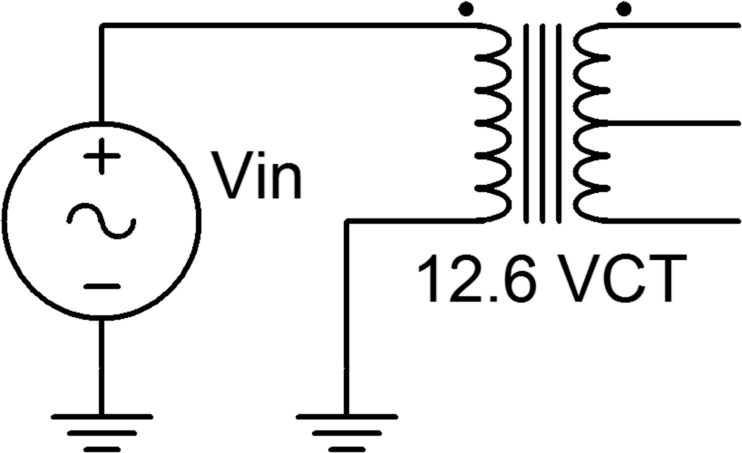
looks like two inductors are in the circuit. We need to tell LTSpice these are transformer. We will use a Spice directive to add a K-Statement ("K Lp Ls 1 ") to this circuit. Click on and add "K Lp Ls 1 ". This will tell LTSpice that Lp is primary and Ls is secondary of the transformer. This voltage can then be used to drive a signal or to control a load. The main advantage of using a pulse transformer triggering circuit over other methods of generating electrical signals is its high efficiency. The transformer allows the voltage corresponding to the input current to be transferred across the isolation barrier without much loss.
How to Build a Transformer Circuit Circuit Diagram
transformer that should be used in an application. For instance, a transformer needed to provide DC isolation between two windings carrying large amounts of currents would be designed differently from a transformer that needs to provide an impedance match to a small signal communications network. In this article, the emphasis will

However, transformers are inefficient in transferring energy if they distort the signal. A wideband transformer can transmit a clean, undistorted low-power signal over a wide range of frequencies. The ratio is used for matching the primary and secondary impedance of the transformer to the circuit into which it is inserted. This ratio is
